Sunday, April 9, 2017

Random photos

"We don't really need this thingy, I hope..."
Before...

Some boats have been on the hard for far too long
My Sasha dreaming of mahi-mahi and flying fish


Training on how to upright a life raft.
...how to put out a fire...


how to survive in open water

...and how to enjoy lunch.

Pulling the impeller.

New base plate welded onto compression post

Taking apart the head to get to the compression post base

Looking for gremlins, Approved Engine Course at MPT 2016

RYA Powerboat Tender Operator Course

Sailboat archeology

My toy, Firefly (now Siren, repainted red)

New compression post base, later discarded in favor of G10 block

Chainplates look good

Overnight fishing, St Augustine

Ft. Lauderdale, 2016

Down to gelcoat

This tool was a lifesaver

My giant pdf, used on oil rigs

Half Moon Bay, California
Maas my neighbor who is a great mentor and teacher on boatbuilding

New internal teak handrails, at shoulder-level

Propane tank locker, part 1

At some point Whimsy had a propane stove, based on the stove gimballs as well as the hole in the galley-side bulkhead for a propane gas line. However there was no dedicated propane tank locker, which leads me to assume that either the propane tank was mounted above-deck, perhaps attached to a stanchion, or more likely the tank was located below deck, inside the port cockpit locker  (this is in the days before the ABYC code, which now requires a dedicated locker for props e tanks stored below deck.)

Yes, it can fit
Naturally I want to do a lot of cooking aboard but I don't want to have propane tanks hanging around outside, off the rail or stanchions, just waiting to be washed away by waves and generally making my boat look bad. So I decided to make a dedicated propane tank locker which is fully compliant with the ABYC code.

I chose to put the locker under the port-side aft-quarter of the cockpit seats. There was mostly wasted space below the seat there, and a convenient place for the propane tanks. Based on my measurements, I could fit two 10-pound tanks into the space, while having enough free vertical space to allow the locker to vent overboard well above the waterline as required by the ABYC.

However, it was going to be a tight fit horizontally, especially as I didn't have a lot of space to create a hatch out of the seating area above the locker. The tank itself was 11-inches in diameter (I rounded up) but the seat was an irregular curved shape that just barely provided enough surface space to cut out a hatch that was large enough to let the propane tank pass through, plus a 1-inch gutter around the hatch to collect water and prevent it from entering the locker (where it could corrode the tank and fittings, even though it would also drain out the vent.)

The locker itself was is integral to the hull. It basically consists of 5 pieces of marine-grade plywood sheathed in fiberglass which form a box under the cockpit seat. The "ceiling" of the locker is the cockpit seat, the bottom of the locker is a panel shaped to conform to the sloped hull and hold the tank upright, and consisted of several pieces that fit together like a 3D jigsaw puzzle. The vent for any leaking propane to escape through, is a 1/2" hole cut through a corner of this box, right through the boat hull. There's no hose connection. The vent is located 5 inches above the static waterline externally.


Making templates for the locker sides

Temporarily glassed-in. The vent hole will be drilled through the locker and hull at this corner


Floor panel, cut to conform to the hull's curved shape. A hole was drilled through the locker and hull in the lower right side of this photo
Propane locker vent is just a hole cut into the hull above the waterline


The ABYC has code standards on the various designs of propane tank lockers. Generally they require a vspor-tight dedicated contsiner with top-opening hatches or lids and that have a vent to drain any leaking propane overboard. The code allows for tanks to be located above-deck (which makes them vulnerable to waves, and looks messy) or in specially-designed but quite expensive sealing boxes that can be placed inside a cockpit locker below deck. Since these boxes are airtight, vented overboard, and their sealed lids can't be opened without the cockpit locker itself being opened to the outside air too, they are deemed acceptable. What is not compliant with the code but apparently popular with boat designers are side-opening propane locker hatches, which would spill any leaked propane.

 I went with the preferred design for a propsne tank locker, which consists of a dedicated locker space below deck that has a hatch which opens directly to the air, and vents overboard of course.  The ABYC has specified in more detail what a compliant propane tank locker like mine requires:

1- It has to be dedicated to propane tanks only, nothing else can be stored in there.

2- The tanks themselves have to be secured and strapped down. I could have gone with one vertical tank but decided on two 10-lb tanks instead, for ease of transport and refill.

3- The locker has to be vapor-tight, so no leaking propane can get into the boat ( propane is heavier than air, so it will tend to accumulate in the bilge,  and then possibly explode when you start the engine.)

4- There has to be a min. half-inch vent that directly drains any leaked propane out of the locker and overboard, above the static waterline (and 20-inches away from any other hull penetration where propane may sneak back in.)

5- Use only approved flexible gas supply hose and connections (or copper pipe, but not in my case) which are supported along the runs, and protected from chafe

6- The gas supply hose penetrates through the propane tank locker via an vapor-tight gland. There can be no T-connections to the gas supply hose outside of the locker, so you can't really use the same supply hose for two propane-consuming items. Rather the gas supply hose has to run directly to the stove, and only to the stove. So any T-connections for other propane-consuming accessories such as a heater or barbecue have to be made inside the locker.  I'm considering one for a spare gas line for my Weber.

7- The gasketed hatch has to open to the outside air, and have a latch. I don't have a latch, just a lifting handle. Gonna have to fix that. It is not as easy as it sounds since the latch will have to be recessed. I may get a nice bronze one to match the rest of the old fixtures in my cockpit if I can find it.

8- There has to be a solenoid to keep the gas supply off at the tank until needed.

9- there has to be a pressure gauge, not to measure the amount of gas left in a bottle (the pressure would remain constant until the bottle is near empty anyway) but to check for leaks.


Propane tank locker hatch closed, flush latch and hinges

Hatch open, showing the drain gutter round the hatch. Had to rush the photo since it was raining


So once the hatch was cut out from the seat, I had to make the gutter to fit under the edges of the newest hole in my boat. This gutter collects and drains any water that may fall on the propane tank locker hatch (rain, or waves.) Designing it was kinda tricky because among other things, the cockpit seats are not "flat" (parallel to the floor) but instead have a back-leaning, knee-raising angle (like any well designed boat should,  so that occupants can sit more securely on the cockpit seats in a heeling sailboat)  so the gutter had to be angled forward to drain water at one particular deep corner, where I cut  a drain hole into the footwell.

The other problem  was with the width of the gutter: the cut-out space needed to for the propane tank didn't leave a lot of space for a gutter to be placed around the hatch too (plus hinges) so the gutter around the hatch was made narrower than what I would have liked, and so I can't easily clean it out of debris such as fallen leaves with a simple finger-swipe as I can the gutters of the locker hatches, so the gutter and its drain can clog and force water to drain into the locker itself. This is a small annoyance, since like I said any water that finds its way into the propane tank locker would drain out the vent hole, though I'd rather not have too much water get into the locker and cause corrosion.

To make the gutter, I drew the shape of the lid and made matching mold using MDF board and gelcoat. The MDF board was then covered in tinted gelcoat, sanded smooth, and thoroughly waxed with mold release wax. This formed the mold.


Then a new white layer of gelcoat was spread over the mold (this would form the exterior of the gutter, so it is already gelcoated once popped off the mold) followed by several layers of fiberglass mat with polyester resin (polyester allows the mat to have better shape conformity than epoxy.)


After a few hours, the gutter was popped off the mold, and epoxied under the newly-cut hatch for the propane tank locker.


More pictures and detailed explanations will be provided in a post about the new instrument panel which was made at the same time using the same process.

The gutter was angled so that it drained water towards a drain hole in lowest corner, and into the footwell. If I had to do it over again, I'd make the drainhole larger. In fact, I may do so now, since it is already hard enough to clean out the gutter.

I still have to finish the project by gelcoating the interior and exterior of the propane locker, change the hatch lift handle into a latching one, install straps to keep the propane tanks secure inside the locker, and mount the regulator, hoses, pressure gauge etc. and then run the gas hose to the galley where I hope to install my cooker soon! See part 2

Centerboard cable reconnected

The Pearson 35 is a shoal-draft centerboard sloop. With the centerboard up, she draws less than 4 feet. With the centerboard down, her draft increases to 7.5 feet. The centerboard itself is a heavy piece of solid fiberglass that hangs from a pin inside the keel.


The centerboard is raised and lowered using a cable attaches to tangs on the top aft corner of the centerboard. The cable runs goes up the keel into the bilge of boat through some brass or bronze tubes that run aft towards the engine, then up through the starboard-side galley counter, ending next to a block mounted over the counter. This block in turn is connected to a 3/8th line that runs to the cockpit via a bulkhead fitting. Pull on the line, the block turns and takes up the cable so the centerboard moves up; release the line & the centerboard drops, etc.

The problem is that in many boats, the centerboard cable has parted so there's no way to lift the centerboard. That was the case for Whimsy too, which is why I had to dig a hole in the ground under her in the boatyard for the droopy centerboard to stay while I worked on reconnecting the cable.
Where the centerboard used to live

Splice eye and saddle clamps to connect to centerboard

Centerboard sheave

Fishing a messenger line through to pull up the new steel centerboard cable


Another sheave that needed cleaning
Of course, when the cable parted, it was pulled up and out of the tubing too, so I had to find a way to fish a new cable through the tubes and out the other end. This was not easy, and all my efforts using a variety of material (including weed-whacker line) failed because, as it turned out, the sheaves were block-up with dirt. I had to take apart all of the tubing and clean the sheaves, before I could run the centerboard cable through and connect it to the centerboard. This was not all that hard and only required a pipe wrench to accomplish.

I used stainless steel cable with an eye and saddle clamps to connect to the centerboard. I had wanted to do a proper steel cable splice but didn't have the time for it. I hope the saddle clamps hold.

I will have to take apart the centerboard cable tubes again, when I build the integral water tank. *Sigh*

Wheel-to-tiller conversion


The Pearson 35 is known for its unique wheel pedestal position, located forward in the cockpit rather than aft, almost pressing up against the companionway. This was because the Pearson 35 was originally designed as a yawl, since CCA racing rules back then didn't handicap or penalize a boat with a yawl rig. Unfortunately the position of the steering wheel blocks access to to companionway a bit. 
   
Steering wheel & pedestal restricts companionway.

Also, as an often single-handed sailor, I was more comfortable with a simple tiller steering system which avoids all the potential problems with steering wheels. Crawling around under the cockpit sole, trying to fix a snapped steering wheel connection is not fun or safe.

That, and the fact that I simply prefer tillers on sailboats (they provide much better "feel" and feedback of how the boat is progressing in the water) made me determined to get rid of the wheel and put a tiller on my Whimsy.

This project was actually not too hard, mainly thanks to the emergency tiller that I salvaged to create a rudder post extension, but also generally due to the fact that the boat seems to have been actually designed for tiller steering, and the steering wheel idea was apparently an after-thought by a manufacturer who was watching the fashion trends...? The location of the emergency tiller made a lot more sense than the location of the steering wheel, but wheels look more "yachty" I guess. However, all of that creates additional weak points in the boat's steering system that can fail, and clutters up the cockpit too. My goal was the reduce clutter and potential weak points, so the steering wheel had to go.


This project involved first removing the wheel pedestal and fixing the rotted cockpit sole around the penetrations through the fiberglass/balsa core.


Sledge hammer and chisel used to remove steering pedestal
Significant rot to be removed


Repaired, filled and faired.

Also, the "guts" of the steering mechanism had to be removed, including the steering wheel chains, steering quadrant, sheaves, pulleys, chains and cables. I managed to get everything out except for two pulleys which are bolted and glassed in. I'll wrestle with them later when I install the autopilot.

Original steering mechanism


Next I removed the inspection port that covered the rudder post below the cockpit sole. This is where the emergency tiller attaches to the rudder, in case something goes wrong with the steering wheel mechanism.

Rudder post top, visible through the removed inspection port on the cockpit sole

The top of the rudder post was just a few inches below the cockpit floor, so in order to attach a tiller arm to this post, first an extension had to be connected to it so it could be raised above the cockpit sole. Also, this extension had to pass through a cylindrical shaftway made of fiberglass, to support it.

Whimsy came with an emergency tiller, a heavy 2"-round piece of pipe made of naval brass with a 45-degree angled end that forming a square socket. This was meant to slip over the top of the rudder post, giving the helmsman direct control over the rudder in case there were any problems with the steering wheel. The emergency tiller head also had two set screws that, when tightened, would prevent it from slipping off the rudder post. However, since the screws were made of steel, they were hopelessly corroded and stuck.

The socket-end of the old emergency tiller, showing corroded set screws


Socket cleaned-up, with new set screws

Since the emergency tiller head had a socket that was already designed to fit over the rudder post, I cut it off and had it welded to an 18"-long piece of round stock made of similar naval brass and with a matching 1.5" diameter, which I ordered from Online Metals. This was my rudder extension post which raised the tip of the rudder post from a few inches below the cockpit floor, to about 9" above it.  (The exact height was left to be determined later, when I got a tiller and practiced using it in the cockpit space to get an idea about its ideal height position before I trimmed down the rudder extension) There was a little play in the socket connection over the rudder post, so I slipped a couple strips of scrap counter-top laminate material  into the joint, and kept them in place with blue tape as I slid the extension piece over the rudder post. No, I'm not worried about the durability of the tape, since once the socket was slipped over the laminate pieces, they weren't going anywhere.

Below the cockpit sole: Rudder post extension fitted over the rudder shaft, held with set screws

  I tapped-in some new set screws that fit into dimples I drilled into the top of the rudder post, thus ensuring that the extension post could not be lifted up & off the rudder post once the set screws were tightened onto the rudder post.

While I had the welders busy on making the rudder post extension using the emergency tiller head, I slipped a piece of PVC piping over the rudder post to act as a temporary extension, thus ensuring that the proper angle with the cockpit sole would be maintained as I built the fiberglass shaftway that would support the extended rudder post.

A PVC pipe slipped over the rudder post acted as a a temporary extension post 

I built the shaftway using a large plastic cup as a fiberglass mold. This too was made initially taller at first, and trimmed down later when I decided on the best positioning with a tiller.

I used several layers of 1707 fiberglass

Newly made rudder post shaft, waiting to be glassed onto the cockpit sole


Next, I bought a bronze Edson tiller head assembly. This has a socket that fits on top of the rudder extension post, and has two tangs or "arms" that hold a wooden tiller arm. I was also lucky to find a wooden laminate tiller arm in very good condition and at a good price at Sailor's Exchange. I only had to trim it about 3" to get the length just right.

Edson tiller head assembly


I also bought a stuffing box, to go around the rudder extension and ensure that no water would leak below.

Stuffing box goes over the rudder extension shaft, which was later trimmed down
I used the wooden tiller as a prop and tried various heights for the tiller head, to determine the best height. I trimmed the rudder extension post and had a new keyway cut into it. After that, it was simply a matter of plopping the Edson tiller head over the now much shorter rudder extension post, and attaching the wooden tiller arm to the tiller head, then trimming it too so it swung freely in the cockpit, over the seats.


I also too opportunity to repack the rudder post stuffing box. After digging out the old stuffing, I used a split piece of PVC tubing that was held in place around the rudder post using a hose clamp, to force the new stuffing up into the stuffing box. I guess we'll see how well I did in repacking this stuffing box when the boat is launched.


In the future, I will be installing an autopilot that connects to the rudder post using a bronze tiller arm below the cockpit. I have the bits and pieces for that project already, just need some time...

Saturday, March 4, 2017

Yes, boats require maintenance

I'm sure everyone is familiar with the ads that show people lounging on a boat in some tropical location, drinks in hand and with no apparent care in the world. This is a lie. Don't believe it.

There is no such thing as the perfect sailboat. Boats are all about compromises, and a major compromise is in the time and effort it takes to maintain a boat. Don't be fooled by the myth of leisurely living on a sailboat, it is actually a lot of hard work and involves long periods of physical discomfort (imagine trying to sleep on a narrow, hard couch as it is violently tossed around the room for days on end, while someone squirts you and your bedding with salt water. That's often what it is like.) The leisurely moments are only rewards for long days and weeks of fixing things, sanding things, varnishing things, hauling things, and buying things. Lots of things.

Any used boat will involve quite a bit of maintenance and upgrades. I have seen even well-maintained boats becoming derelicts after just sitting in a slip for a couple of years, as gaskets and seals rot away, pipes and hoses dry up and crumble, as the relentless sunshine and humidity degrades everything onboard. Just keeping up with that a constant battle.

Relying on others to do the work is foolish, since no one will ever care about your boat as much as you, aside from the fact that finding a qualified and honest contractor is actually quite hard (never mind the cost!) I was well-aware that boats will require much more maintenance than planned, and that any project will inflate into a much larger one quite quickly...but the amount of work required is still quite surprising.

Boats require maintenance. I have yet to meet anyone whose boat is actually in perfect condition and required no additional work. Personally, I don't consider that negative at all, and in fact I enjoy working on my boat very much. More importantly, since the Master of any vessel (notice I didn't use the term "Captain") is always totally responsible for everything that happens on their boat, and since no one can really expect to get mechanical help quickly enough in case of an emergency while at sea, it is very important to get to know everything about your boat and how to fix any problem that may arise. Lives are quite literally at stake, and if something goes wrong, you can drown just as easily a few yards from land as miles offshore. Small issues can quickly add up to big problems. You need to be familiar with literally every wire, every nut, every bolt and every fitting - and you have to expect and be prepared to act when any one of these fails catastrophically in dire circumstances -- and there's a good chance they will. Fixing up a boat should therefore not be seen as a distraction but rather as a very important part of seamanship, because it is the only way to really learn your boat.

So in short, if you're in the market for a sailboat, make sure you know what you're getting into, and that you are willing to commit both the time and resources to manage a steep learning curve.

This is the only bit of moralizing you can expect on this blog, aside from an up-coming rant about drunks and careless boaters.

Restoring a classic Pearson 35 sailboat

Welcome! This is a blog about restoring my 1967 Pearson 35, hull no. 35. Since I learned a lot from the various blogs, videos and comments posted online by others, I hope to return the favor and contribute my experiences with this project in the hope that it may be helpful to others, especially first-time boat owners and dreamers.


The boat was purchased in the early summer of 2015 and is undergoing a full restoration and refit in St. Augustine, Florida (close to a Home Depot and a Westmarine branch as well as the famous Sailor's Exchange store, where I spend hours scouring through piles of old boat parts for classic bits-and-pieces which are no longer manufactured.)

Pearson Yachts was a venerable brand name among American boatbuilders, and their older models from the late 1960's and early-70's have a good reputation as stoutly-built and sea-worthy vessels with thick, solid fiberglass hulls. They went out of business in the 1990s, and the last Pearson 35 was built around 1980, with about 500 sold in total.

Designed by Bill Shaw, the Pearson 35 is a 35-foot (10.7 meter) mast-head sloop with a water-length of 25 feet.  A full keel and displacement of 13000 lbs (6 metric tons) means the Pearson 35 was designed conservatively by today's standards, making for a safe and easy-to-handle boat. Based on the CCA design rules of the day, the Pearson 35 has long overhangs and a narrow beam of 10 feet (3 meters) and is today classified as a moderate to heavy-displacement cruiser (sail area to displacement ratio: 15.9)

Any sailboat design is a compromise between various competing considerations. In selecting a boat, my primary concern was safety, followed by versatility and ease of handling. I selected the Pearson 35 model because it met my requirements, and they are generally less expensive than similar-sized sailboats of the era due to the centerboard, which many potential buyers wrongly assume presents a significant headache.


On my boat, the first project was re-attaching the centerboard cable that had parted.  This was really not such a big deal. All that was necessary  was a pipe-wrench and a few feet of stainless steel wire cable with an eyesplice. Of course you have to pay a bit more attention to the compartment where the centerboard lives when scraping the hull clean of marine growth, and that's really about it. Oh, should the cable part again, don't yank it out all the way!

The centerboard increases the draft from just under 4 feet (1.2 meters) when raised, to 7.5 feet (2.3 meters) when lowered.  A shallow draft allows easy access to many marinas, inlets, harbors, and bommie-strewn bays where other boats dare not venture. Gunkholing becomes much easier when you don't have to worry about draft, and I can anchor a few feet from any sandy beach in waist-high waters. Since my cruising grounds are primarily off of the Florida Keys and the Bahamas, this is an important consideration, plus there are no problems finding an anchorage or passing under ICW bridges, etc. Hauling up an anchor using a manual winch from just a few feet of water is much easier too. There's also a safety benefit in being able to find shelter quickly and easily in shallow waters in case of a sudden and unexpected change in weather.

Naturally the centerboard cable on my boat had parted and was pulled out of its tube all the way, requiring me to reconnect the centerboard cable (and then later disconnect and reconnect them again when I made integral water tanks in the keel.)

Some reviewers claim that the large, nine foot-long cockpit of the Pearson 35 is a liability offshore since she can ship a lot of water if pooped, but increasing the size and number of scuppers easily resolves that concern. I don't really plan on battling too many major storms anyway and would rather avoid them, so getting pooped is not a major concern. (Years of accumulated data by the Coast Guards show that the biggest threat to boaters is alcohol consumption by fellow boaters, by far.)

The initial survey showed no real big surprises for this particular boat, which came with no extras such as electronics or after-market gear that would only add to the headaches in a refit. The boat was judged to be in "average" condition by the surveyor, with the usual problems expected of a boat of this age. However, the engine, wiring and other fittings were in good shape, as was the rigging. The mainsail is in good shape too, with many years left in it. I will add  lazy jacks, and a Harken roller-furling foresail, and may replace the shrouds and turnbuckles just to be sure though they are in good shape.

The most significant problems were the small wet spots in the deck around some fittings and the mast base. The deck-stepped mast is supported below by an aluminum compression post, which is itself supported by a block of wood sheathed in fiberglass.  On my boat (and many others) this block of wood rotted away long ago and had turned into a wet sponge (the shower pan and anchor locker drain hoses ended right up against the compression post block!) causing the mast to press down into the deck. In turn, that led to water intrusion around the mast base into the balsa core of the deck. I had to dig out the wet balsa core there, and replaced it with a thick G10 fiberglass sheet.


Compression post base - where are the bolts? Never found them.

A wet sponge was holding up the mast compression post!


The wooden block below the compression post was also replaced with a 3-inch thick block of G10, which was probably overkill. There were also a few wet spots around a couple of stanchion bases and cleats. Since I planned on re-bedding all the deck fittings anyway, using more substantial backing plates than the original fender washers and wooden (dry-rotted) backing plates fixing these wet spots was inevitable.

 My goal in restoring the boat was first to "Keep It Simple" and to try to keep as much as the original character of the vessel as possible, especially the 1960's-style interior. I also wanted to make her easier to sail single-handed so I replaced the steering wheel with a tiller (ridding myself of the complications of the steering quadrant, chains, pulleys etc., while also significantly opening up the cockpit space) and upgraded her old winches to larger-sized self-tailers. I also plan to remove the traveler entirely in favor of end-boom sheeting, add telescoping emergency boarding ladders on each side, and move the water tank from the bow to under the settees.

New electronics will be added, including full instruments, radar, AIS transponder, autopilot, wind monitor, VHF with RAM, and two Raymarine multifunction displays for the cabin and cockpit helm. I was considering lithium-iron batteries but have decided to hold off on that for now, until the kinks are worked out of the technology (after witnessing one boat on fire as a result of poorly-designed lithium batteries with corroded connections and too-tight packing of the cells resulting in too much heat accumulation, I had second thoughts about the batteries.) I'll exchange the wet-cell battery with larger capacity AGMs and add a starting battery, as well as solar panels on a hard bimini that I will build too.

Of course, I have all the latest safety gear, including a Viking 4-person valise liferaft, two EPIRBs, and four sets of offshore PDFs (each with their own PLBs and lights) and a LifeSling system. I also invested in a MOB alarm, particularly for any kids on board. I decided to forego an SSB radio in favor of a satellite tracker and telephone. I also added teak handrails inside the boat, at shoulder level below the portholes. The automatic bilge-pump will be replaced by two larger capacity models, with a high-water alarm. Naturally I will add fire, carbon monoxide and propane alarms too. I also have a spare anchor, a Fortress stern-hung anchor, a sea anchor, and a drogue.

All the portholes were removed and replaced with a total of eight opening portholess, which significantly improve ventilation below. The original small, oval-shaped portholes were not of much practical use anyway, and the large fixed ports were starting to leak.

I also added salt-water faucets in the galley and head, and an electric washdown pump in the bow. (I am considering placing a fresh-water washdown pump in the cockpit. It would be convenient to shower, rinse off diving gear, etc. but it would also increase fresh water consumption, so...)

Other upgrades to the galley include a new Dometic stove with a dedicated propane tank locker, and a new stainless steel sink, as well as a wall-mounted manual coffee grinder  (no power consumption, and single-handed operation -- very important on a heeling sailboat.) I have not yet investigated the icebox and don't know how well that works, though it seems reasonably functional.

I'll install new fans and new LED lighting, as well as a new tricolor masthead light and spreader lights. A 400-watt stereo system with 4 speakers, plus a DC-powered LCD monitor, all connected to a laptop computer loaded with navigation apps which is safely tucked way in a waterproof compartment and operated using an illuminated wireless keyboard, complete the electronics upgrades.

I am also redesigning the anchor locker and adding a hatch on deck instead of using the v-berth hatch, adding new teak hand rails inside and outside the cabin, as well as folding mast steps. I don't want a windvane or wind generator but I will carry a large-capacity car booster battery for back-up power. No pressurized water, water heater, air conditioning etc. either.
         
I am now in the process of repainting the boat entirely. This is probably the hardest project since it is not only very time-consuming but also very detailed and hard work. It took months to remove all the old fittings, the nasty old nonskid that was itself mixed with sand and therefore impervious to my sander, and the damaged gelcoat underneath that. Filling, fairing, sanding and priming the deck under the hot Florida sun, while tormented by vicious no-see-ums and other biting insects, and while covered in fiberglass dust, was no fun at all.

I have to also paint the ceiling of the cabin interior. The old paint comes off in strips, Removing the old paint is not an easy job since sanding or grinding will remove the texture pattern on the cabin liner, so I can't just take a grinder to it. I'm considering using paint stripper, heat guns, wire brushes and 3M Roloc bristle disks for that job.

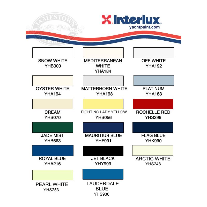
Currently the boat has a navy blue hull. Dark colors are too hot for the tropics, and the paint is chipping off anyway, so I plan to go with Interlux Perfection Fighting Lady Yellow. The deck will be white. I'll be using KiwiGrip nonskid paint too. Since painting with two-part paint is really an art, and getting a good finish using the roller-tipping method is MUCH harder than painting a house with latex paint, I had to practice a lot on a dinghy. It took several layers of paint before I "got the hang of it" with a reasonable finish. I still don't have it down pat -- you can see the lines between patches if you look very closely. Too closely.

Anyway, please visit regularly as I plan to update this blog more often now.