Monday, September 5, 2022

Installing a Dorade box vent on my sailboat

Adequate ventilation inside a sailboat's cabin is a must, whether in the hot tropics or colder climates where condensation becomes a problem. Being stuck inside a hot damp boat interior with no fresh air circulation is a miserable experience especially on passage, or even on a rainy day at anchor, when opening the portlights or top hatches is not an option. 


Dorade box vent dry-installed; Vetus Samoen silicon cowl

Whimsy will have 8 opening portlights (7 on cabin sides and an aft-facing one over the galley sink) but because boats tend to point into the wind, cabin-side opening portlights are generally not as effective in promoting air flow. A forward-facing portlight is also not an option as the force of waves crashing over the bow can possibly stove-in the area, not to mention the leaks. The solution is a Dorade box vent.

 Dorade vents are named after the Olin Stephens-designed sea-racing yacht Dorade built in 1929 when the Robber-Barons took up pleasure sailing, which is surprising because it seems like such a simple solution to a common problem that should have been invented much earlier: how to get air ventilation below deck without letting water in too.

A Dorade box vent basically consists of a rotating cowl that can be pointed into the wind, attached on top of a teak box that has an internal baffle,  which is placed over a hole on deck. The idea is that the internal baffle will keep out most of the sea spray and rain, which drains out from the bottom of the box, while the air moves over the baffle, down the hole & into the cabin. 

Getting air into the cabin is part of the deal; there also has to be adequate air exhaust routes for proper ventilation to occur. A Dorade box cowl can be pointed away from the wind too, creating negative pressure that will tend to suck air out of the cabin. This is why larger boats can have pairs of Dorade box vents: one facing fore and one facing aft, creating a continuous draft through the boat interior. 

Whimsy doesn't have the deck space for two vents and won't need one because the companionway as well as the yet-to-be installed aft-facing opening portlight over the galley sink, will provide enough of a passive air exit. They will in turn be protected from rain and spray by the yet-to-be installed dodger.

Parts for this project consisted of an off-the-shelf teak Dorade box, a cowl whose base just barely fit over the box, and a ring cut off of 5"wide PVC pipe.


The cowl is the most problematic part. One of the issues with Dorade box vents, other than their primary drawback which is taking up large tracts of deck space, is that the cowl can be a nuisance, fouling lines and banging shins. Traditional Dorade box cowls are fancy highly polished, hard metal objects with sharp edges that look pretty but a jibsheet caught around a Dorade box cowl can potentially rip it right off, and I'd hate to trip onto a cowl. Traditionally the solution was to build a steel cage around the vent to prevent all that, thus taking up yet ore space and not reducing trip hazards. 

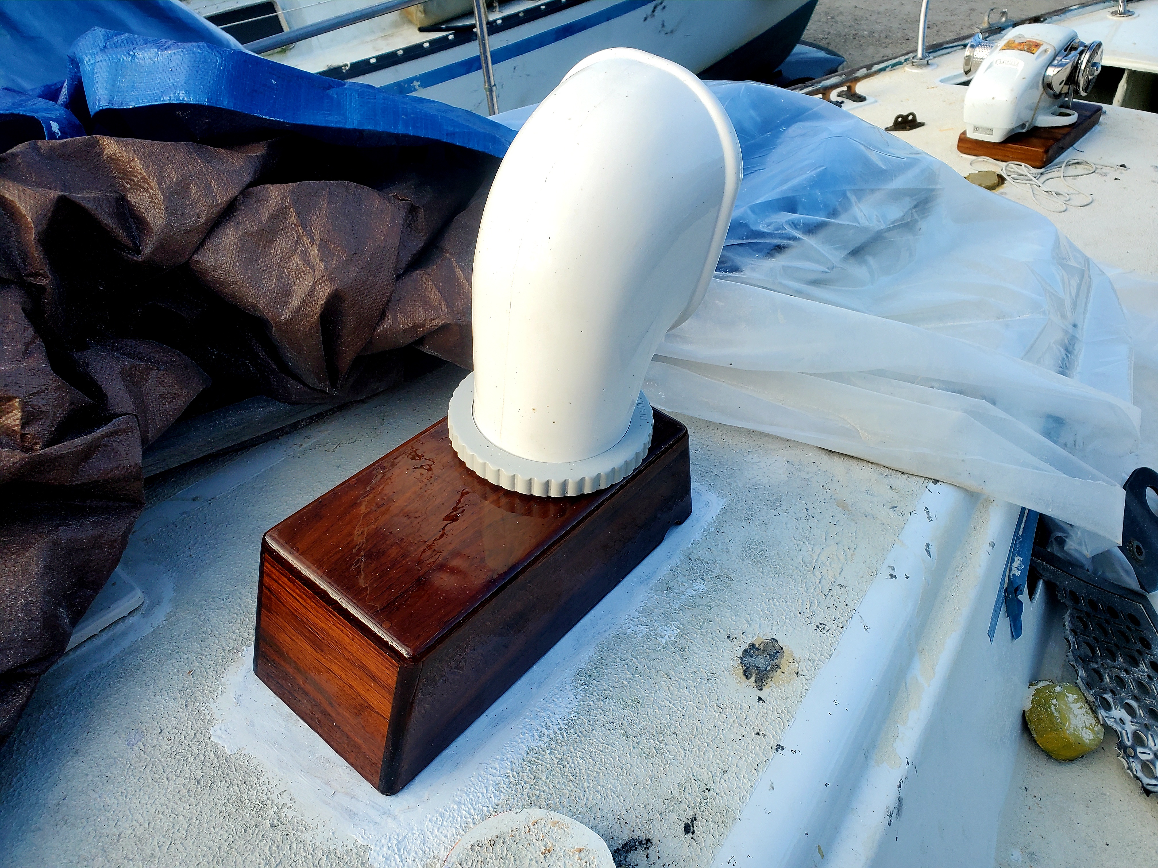
Manufacturers came up with PVC cowls that are flexible enough not to foul lines and to not cut you open if you should fall on then, but the general consensus is that they don't fare well under the sun and also tend to stain, turn yellow or mildew. Vetus however has come up with soft but rigid cowls made of silicon, which supposedly fares better than PVC under the sun. I guess we'll see but the material doesn't feel floppy as I had feared.  Anyway I got the biggest cowl I could find to maximize airflow: the Vetus Samoen cowl with a gaping air scoop painted red and 5"-wide opening hole on the base. 

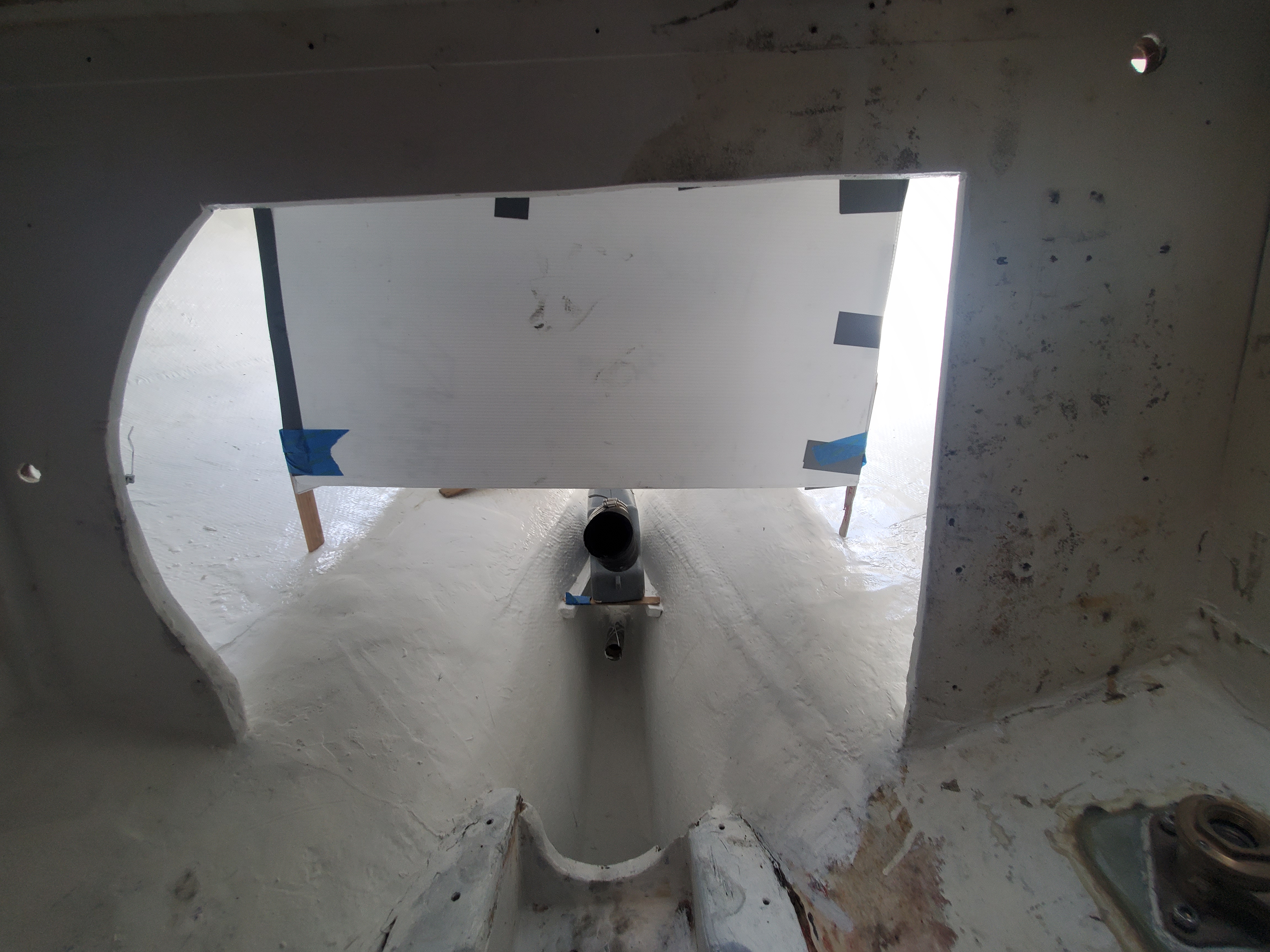
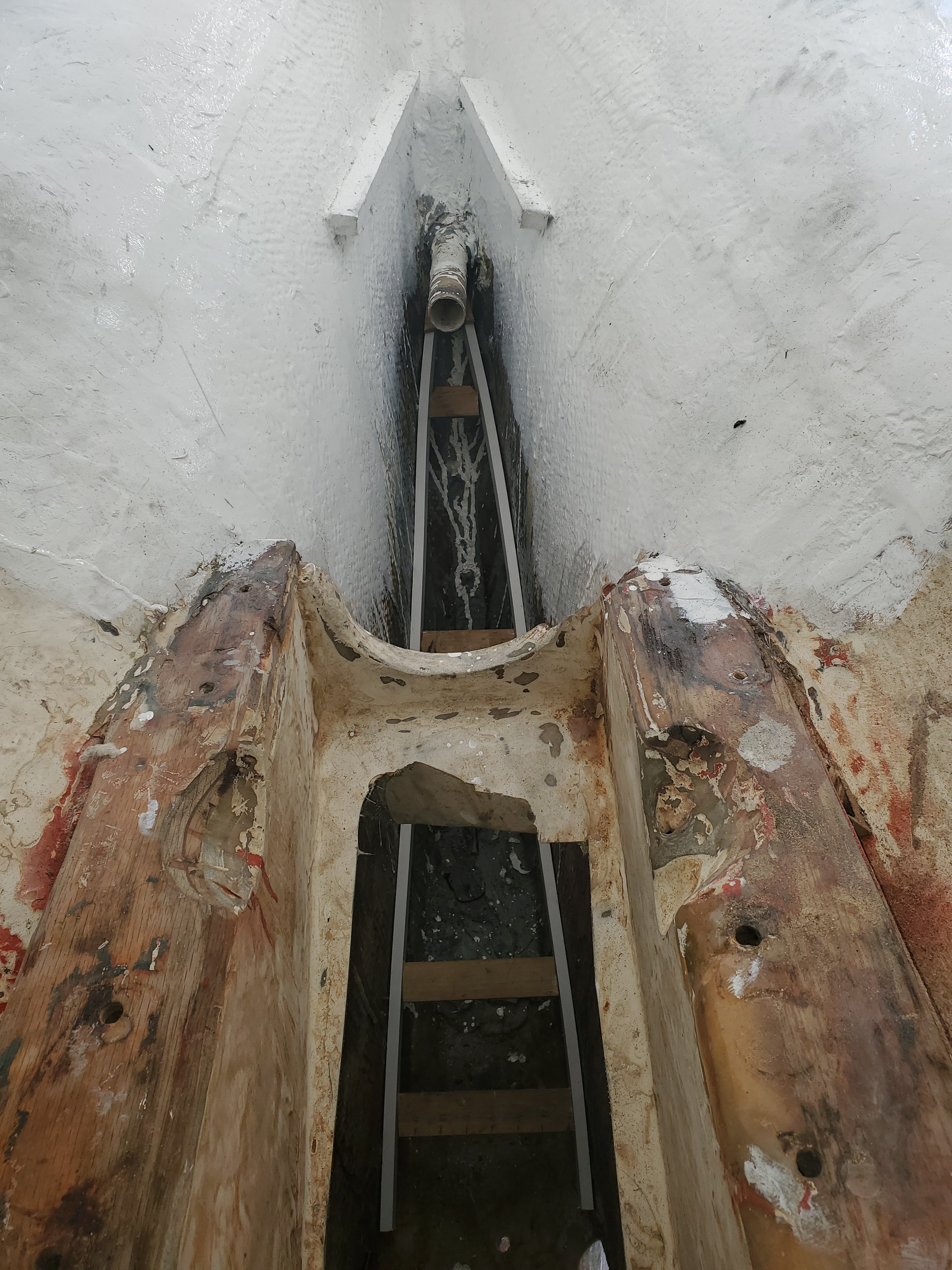
The installation of my Dorade box vent was pretty straight-forward as there aren't too many places to install one on deck. I was most concerned with making sure it did not interfere with any lines running aft to the cockpit. Then, installation was simply a matter of cutting a 5" hole on deck, and a slightly larger hole from below (for the cover plate). I went through the usual process of scooping out the balsa core material and filling the gap with epoxy filler. I had cut off about  2" length off of a 5"-wide PVC pipe to make a plastic ring; this was installed over the deck hole with about a 1" tall lip sticking up, acting as a dam to further limit water intrusion around the deck hole. Then a few coats of gel coat, and the quickly "varnished" teak box was stuck on the deck top with 3M 5200 only (I don't see any reason why it would need to be more securely fastened on deck, and additional fasteners just mean more holes for water penetration.) 

To close up the Dorade box vent from below, a 5" (internal diameter) waterproof plastic deck plate was installed from the interior under the hole. 

I decided to varnish the teak box. Though teak tends to be naturally weather resistant, I was concerned as the boards used to make my Dorade box were kinda thin, and so could use protection. I also like the glossy look of varnished wood. The quick-and-dirty varnish job was just two coats of epoxy (first one was Totalboat "penetrating" epoxy, as teak tends to be oily & not stick well to epoxy resin) followed by two coats of Interlux Perfection Plus to give it a glossy look, as well as to protect the epoxy from the Sun's UV.  The final coat was a spray of glossy acrylic from a can with additional UV inhibitors; not strictly necessary but helped deepen the gloss.. Of course there are drips and dust specks galore; I am working in a dusty boatyard. 

So, now Whimsy has pretty much maxed-out the natural ventilation options. Combined with multiple fans, there is not much else that can be done to improve ventilation below, but for a small screen on the cowl to keep out bugs.


Friday, May 6, 2022

Filling-in the bilge sump; restoring engine bay and area below cockpit


 I have been very negligent in updating this blog mainly because restoring boats is simply not an orderly, chronological process that moves ahead in a linear fashion; in reality I may be working on 5 projects of which 2 may be progressing while 2 are not and 1 is going backwards. In the meantime, all sorts of other stuff can happen, like pandemics or invasions... This means I don't really have many actual, totally completed projects to present. Everything seems to be pending something else. The illusion of orderly, consistent progress on diy sites is false!


Making sure new fuel tank can clear water muffler and exhaust hose (which previously chafed under old fuel tank cradle)


However  there are a few projects that have enough progress to be worthy of an update post. Clearing out the engine bay and restoring (improving!) the area under the cockpit sole was one such project, though that too is not really "done." Nothing is! 

My goal was to clean up the engine bay, remove the old fittings, wires, hoses etc  and also fill in the bilge sump, which is the deep dark inaccessible crevice under and behind the engine, then paint whole area before installing new fuel tank and the rebuilt engine. 

This area is quite inaccessible. Even without the prop shaft in the way, it is just too deep to reach. Anything that falls in there is pretty much a goner & there would be no way to address a hull breach if for example the boat should back up on a bommie. So now with the engine and fuel tank out, filling up the area with marine expanding foam and glassing it over permenently was a priority


Test fitting a dummy fuel tank. I think I may be able to go from 26 gal poly tank to a 50 gal aluminum tank.


Pouring in the expanding foam. I used three 32- Oz mixtures but poured them in only after giving the previous mixture time to expand. 


The end, with coat of two-part paint over gelcoat (easier cleaning) and waiting to install autopilot ram arm.


Gelcoat over the foamed-in and then glassed-in bilge sump area, started from just under prop shaft log (whole other post about that soon too!)  Also seen: the two supports for the shelf where the water muffler will live. 


I filled in the area with 6lb expanding foam, poured through a hole cut into the cover plate. The trick is to go slow. 


The hole where the expanding foam is poured in. 
Because of tight space under the prop shaft log, I could not pour in the foam from all the way at the top. So the last few inches on the top were filled--in with hardware store gap filler foam before being glassed-over and sealed permanently


Accidentally took a selfie


The cut-out "lid" fitted diagonally over the bilge sump area, cut out of 1/4" pvc sheet, being glassed-in.


Using battens to make a diagonal template of the bilge sump area. Diagonal because the bilge pump hoses must pass through here, under the engine cradle, and the leaks if any from the prop shaft packing gland will roll forward (along with any tools dropped in here now)


I cut a hole in the engine cradle bed to allow easier access under it. I also cut a 2" hole in the hull to allow easier drainage to clean out the bilge sump

The area immediately under the engine will not be filled because the bilge pump hoses will pass through here. (A bottle-jack placed here under the engine will make it easier to move and align the engine too.)


The stuffing box or packing gland for the prop shaft cleaned up well with a quick acid bath. Whole post on that later!


See the drain holes cut under the hull? Washing out 50+ years of stuff in the bigle sump was not easy. I will plug these drain holes permenently later


The packing gland and prop stuffing box
A whole post dedicated to this is coming later but note use of regular exhaust hose with wire, as a stuffing box hose (held with the old serrated hose clamps.) These will change when Iget around to redoing the packing gland


There was a lot of sloppy fiberglass work that had to be ground-away.  Two pieces of timber seem to support each side of the cockpit but the glassing around them, where buyers were unlikely to check, was a mess with giant fist-sized globs of filler and poorly adhered matting. 


Before. Yuckie!


Thursday, January 6, 2022

Marine diesel engine rebuild, part 1: removing propeller and shaft

WHIMSY came with a Beta Marine 28 diesel engine built in Sept 2000. This is a marinized version of the Kubota BD 1005, meaning among other things that it is cooled by a seawater heat exchanger rather than with a radiator and fan like in a car. They've also added a convenient handpump to make oil changes easier, but mine has been dangling in a wet bilge apparently and has rusted bits that will need replacing. The engine paint is chipped off, there are bits of corrosion and rust, etc.  However, despite cosmetics, diesel engines in general are tough, and will run forever as long as they get regular TLC in the form of clean fuel, regular oil changes and plenty of ventilation. 

Though I discovered the anode zinc pencil on the heat exchanger had been eaten away to a nub, suggesting poor maintenance and additional possible damage to the heat exchanger, the engine ran fine when I had the first test sail back when I first bought the boat. It has been sitting around since then, gathering dust. I can turn the prop shaft in both directions easily so I don't expect it is siezed. I needed to pull it for a rebuild, including head gasket change, and to make improvements (larger capacity alternator, for example, to handle charging a large lithium LiFePO battery bank) 

I wanted to get access to the bilge area and the area under the cockpit too. I plan to generally clean, fill-in the areas of the bilge that are inaccessible by hand (under the prop shaft log in particular) and paint the entire area with white gel coat followed by anti mildew paint on the upper areas (as in the anchor locker, which also tends to be a dark humid environment.) While the engine is out, I plan to reroute bilge drain hoses, install the autopilot, etc. The galley sink drain standing pipe is an open question, I may just glass-in and brace the drain standing pipe more securely, or seal it up and reroute the galley sink drain through a sump pump arrangement overboard above the waterline? I am tending towards the latter for safety though it will be more inconvenient to clean out a sump pump of bits of food and grease.

I also need to repack the prop shaft stuffing box. I had considered a watertight shaft seal but I think this many-hundred year old solution to having a rotating shaft through a hole underwater without leaks, is a pretty good one as it is, even though there will be a constant drip from the stuffing box. Maybe I'll find some way to direct the drip into a the sink sump I was thinking of building...

So anyway, the first thing to do is to remove the propeller, to be able to further disconnect the prop shaft from the engine transmission box. After removing the prop nuts, my prop just popped off easily using a gear puller, no drama no fuss. I just had to push the rudder hard to starboard to get the prop entirely off the prop shaft. The prop shaft zinc anode is new, and I had the cutlass bearing changed already.

Checking the prop, it has some minor nicks but seems fine. I noticed it had a nylon bushing, so it was probably designed for a 1" shaft, while WHIMSY has a 7/8" prop shaft. The bushing may be responsible for the wear on the prop shaft key, so I guess I am buying a new propeller and saving this one as a backup. This is a three bladed 12" diameter bronze prop, so we're talking about $500 new. (Have to figure out the old prop pitch.)

The prop shaft coupling unscrewed easily, though it looks very rusted. It includes an R&D flexible coupler to take-up torsion forces. Ideally I'd like to install a thrust bearing and cv joint (but I don't think there is enough room left over along the drive train that would allow me to also service the stuffing box.) As it is, the forward force of the engine is transfered to the hull via the engine mounts, which is not ideal; a thrust bearing would remove that force off the engine mounts, and the cv joint would resolve alignment issues. (When installing marine diesel engines,  you're supposed to make sure the the prop shaft coupling is aligned to the transmission correctly, checking with feeler gauges, but there is now way to check alignment once the engine is operating. CV joints actually require a little misalignment. )

Once the coupling was unbolted, it was easy to just pull the prop shaft from inside the engine compartment. I had made sure there were no bolts or keys on the other end of the shaft before just sliding it out of the stuffing box. 

The prop shaft seems fine, there is no corrosion, no groves, etc.and no indications that it was rubbing inside the shaft log due to misalignment Prop shafts often are subject to electrolytic corrosion due to stray current, or crevice corrosion esp. in areas along the stuffing box, where the packing deprives the steel of oxygen. The problem is that what may seem like surface discoloration can be evidence of very deep and so invisible corrosion on a prop shaft. Mine thankfully had no issues though I was surprised how short my prop shaft was, about 3 feet. 

Anyway, because I had pulled the prop shaft from inside the boat, there was no need for me to remove the coupling itself off the shaft. This was a relief because with the very rusted set screws on the coupling, I could tell this was a job for a professional machine shop (that will probably end up cutting off the coupling: if you do this, make sure to cut the coupling over the shaft key, to protect the prop shaft itself in case you cut too deeply, then use metal wedges to loosen the coupling off the shaft. If you do manage to get the coupling off easily by just undoing the set screws and using a coupling removal tool (or maybe you have a split shaft coupling, which consists of two parts bolted together over the prop shaft which can be removed much more easily) note it is generally a good idea to not reuse old couplings since they may be warped. Installing a new coupling on a prop shaft should also be done at a professional machine shop to make sure it is mounted square to the shaft. If the coupling itself is warped or misaligned, then the prop shaft and engine will never be aligned right, resulting in excessive transmission and prop shaft wear, maybe even a permanently damaged prop shaft or engine. A new one-piece coupling is about $70.